Overview
For those on a budget or with simple needs, Microsoft’s server operating system includes a built-in network load balancer feature. Windows NLB, as it is typically called, is a fully functional layer 4 balancer, meaning it is only capable of inspecting the destination IP address of an incoming packet and forwarding it to another server using round-robin.
The figure below depicts an incoming request hitting a layer 4 load balancer. The request is then forwarded to one of three web servers in the cluster.
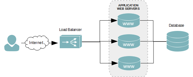
With most load balancers, the service sits on an external appliance, as seen in the figure above. With Microsoft’s NLB, however, the web servers in the cluster are also the network load balancer. Each web server in the cluster hosts the floating IP address – known as the NLB cluster IP address.
Network Infrastructure Scenario
I will be using the following infrastructure to create a load balanced web server using Microsoft’s NLB feature.
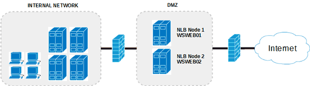
The server will have two network interfaces and will be multi-homed. This allows us to dedicate one NIC to server management and the other to our website’s Internet traffic. The servers will also reside inside of a DMZ to protect our Internal network.

Both network interfaces have been renamed, as can see in the figure above, to make it easier to identiy their functions. The Management interface is for internal remote connections, and the NLB is used by the cluster and accessed by users of the web site.
Web Servers
The two web servers will have the following configuration.
| Hostname | Mangement NIC | NLB NIC | Role | Cluster | Cluster IP |
|---|---|---|---|---|---|
| WSWEB01 | 172.30.0.100 | 172.30.1.21 | IIS | contoso.com | 17.30.1.20 |
| WSWEB02 | 172.30.0.101 | 172.30.1.22 | IIS |
Multi-homed Network Routing
Our servers are all multi-homed, which means they each connect to two different networks. Since a default gateway can be configured on only one network interface, we need to create custom routes for the other. We’ll assign the default gateway to the Internet facing network interface and create custom routes for our internal network.
Without the custom routes, remote connections from the internal network, such as RDP, will find their way to our web servers; however, connections back to our client computer initiating the RDP session will not be able to find their way back. This, of course, prevents you from logging onto the server or managing it from the Internal network.
- Open a Command prompt.
- Run the route command to get the interface index value of the management network interface.
route print
- At the beginning of the route command’s output, you will see an interface list.
Microsoft Windows [Version 6.3.9600]
(c) 2013 Microsoft Corporation. All rights reserved.

C:UsersAdministrator>route print
===========================================================================
Interface List
 25...02 bf ac 1e 00 82 ......Intel(R) 82574L Gigabit Network Connection #2
 12...00 0c 29 16 8c 1a ......Intel(R) 82574L Gigabit Network Connection
  1...........................Software Loopback Interface 1
 13...00 00 00 00 00 00 00 e0 Microsoft ISATAP Adapter
 14...00 00 00 00 00 00 00 e0 Teredo Tunneling Pseudo-Interface
 29...00 00 00 00 00 00 00 e0 Microsoft ISATAP Adapter #2
===========================================================================
- By knowing the MAC address of our management network interface, which is 00 0c 29 16 8c 1a, I’ve determined the interface index to be 12.
12...00 0c 29 16 8c 1a ......Intel(R) 82574L Gigabit Network Connection
- In my lab environment, there are three internal subnets that this server may receive a connection from on the management interface. I need to create a route for each of the following subnets.
Subnet 10.4.0.0 /24 10.5.0.0 /24 10.6.0.0 /24 Gateway 172.30.0.1 Each route must be assigned to interface index 12 – our management interface in this tutorial. All routes must go through our gateway at 172.30.0.1. Use the route command to create the routes.
route -p add 10.4.0.0 mask 255.255.255.0 172.30.0.1 metric 1 if 12
route -p add 10.5.0.0 mask 255.255.255.0 172.30.0.1 metric 1 if 12
route -p add 10.6.0.0 mask 255.255.255.0 172.30.0.1 metric 1 if 12
The -p argument makes the route persistent, which means it’s permanent and will survive a reboot. The metric value of 11 for each route is their routing cost. The lower the cost the more preferred the route is, which ensures communications back to those three subnets are not attempted over our Internet facing network interface.
Install the NLB Feature
This step needs to be followed on all servers that will be added to the cluster. Log onto each using an account with administrative rights and follow the instructions below.
- Launch Server Manager.
- Click Manage.
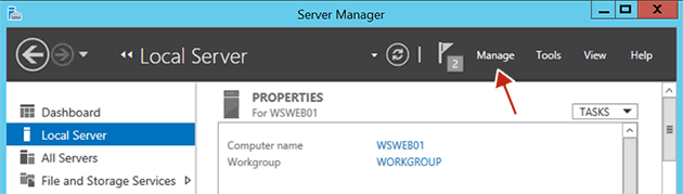
Click the Manage link in Server Manager - Click Add New Roles and Features.
- On the Before you begin screen, click Next.
- On the Select installation type screen, select the Role-based or Feature-based installation radio button, and then click Next.
- On the Select destination server screen, ensure the Select a server from the server pool radio is selected. Now ensure the current server is selected in the Server Pool.
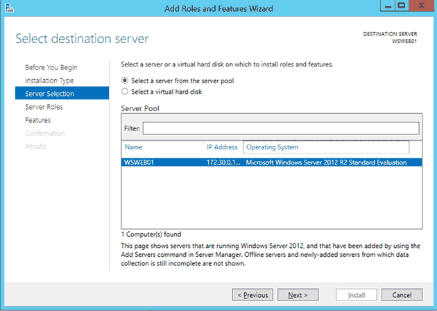
Select destination server - Click Next.
- On the Select server roles screen, click Next.
- On the Select features screen, scroll down the feature list and check the Network Load Balancing checkbox.
- Click Next.
- On the Confirmation screen, click Install.
Create an NLB Cluster
- Launch the Network Load Balancing Manager. This can be done by clicking the Tools menu in the Server Manager.
- From the top menu of the Network Load Balancing Manager, click Cluster, and then click New.
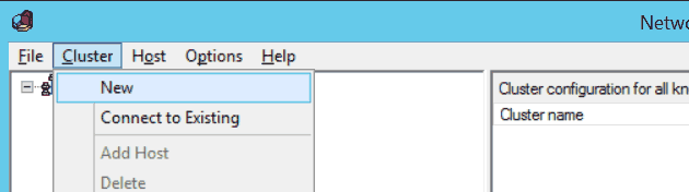
NLB New Cluster - In the Host text field of the New Cluster : Connect dialog box, enter an IP address of the server you are currently logged onto.
- The Interfaces available for configuring a new cluster table will then populate with the network interfaces of the server. Select the NLB interface and then click the Next button.
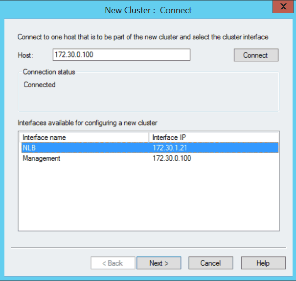
NLB New Cluster Connect screenshot - In the New Cluster : Host Parameters dialog box, click Next.
- In the New Cluster : Cluster IP Addresses dialog box, click Add…
- Enter the IP address and the subnet mask you want to assign to the web server cluster. When done, click OK.
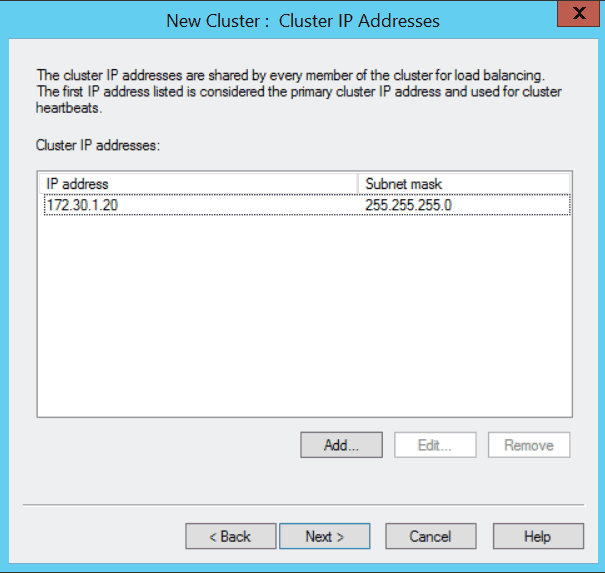
Windows Server 2012 NLB New Cluster Cluster IP Addresses - Click Next.
- In the New Cluster : Cluster Parameters dialog box, enter the FQDN you are going to assign to the cluster. When done, click Next.
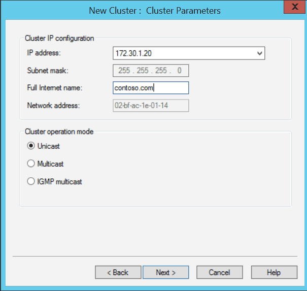
Windows Server 2012 NLB New Cluster Cluster Parameters - We are only serving web content over port 80. Let’s narrow the port rules down to only accept connections to the cluster over that port. Select the default rule and then click Edit.
- In the Add/Edit Port Rule dialog box, uncheck All under Cluster IP address. Ensure the IP address we’ve assign to the cluster is selected in the drop-down menu.
- Under Port Range of the Add/Edit Port Rule dialog box, enter 80 in both the From and To text fields.
- Under Protocols, select TCP. For this web balance cluster, we will not need UDP.
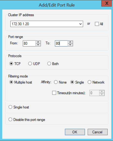
NLB Cluster AddEdit Port Rules - Keep the remaining default settings and then click OK.
- Click Finish.
- The NLB cluster will now be created with a single node (WSWEB01).
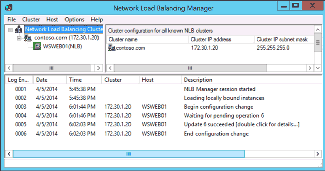
Windows Server 2012 NLB
Add the Second Web Server
Load balance clusters typically have two or more nodes, and ours is no exception. It’s time we add the second web server to the cluster we just created.
- In the left tree-view panel of the Network Load Balancing Manager, select the name of the cluster we just created (contoso.com). If you don’t see it, expand the Network Load Balancing Clusters tree node.
- Right-click the cluster name and click Add Host to Cluster.
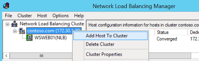
Add Host to Cluster dialog box in NLB - In the Add Host to Cluster : Connect dialog box, enter the IP address of the second web server.
- When populated, select the Internet facing network interface in the Interfaces available for configuring the cluster list of interfaces. Like the first node, ours is named NLB. When done, click Next.
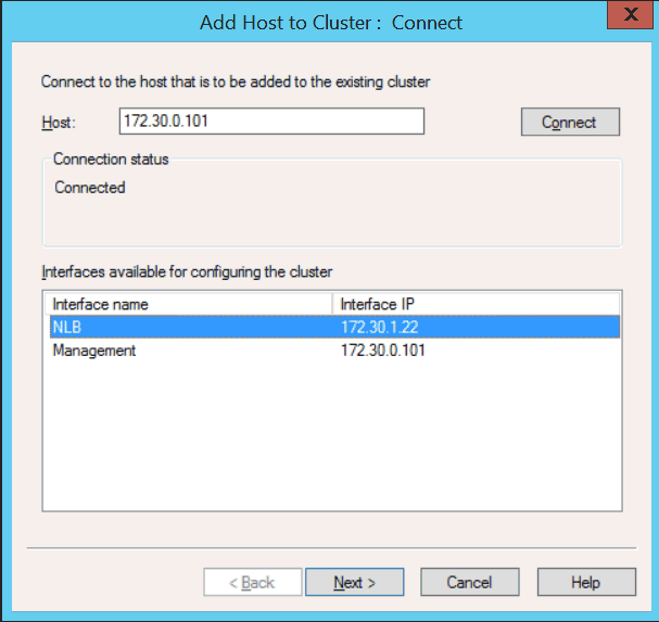
Windows Server 2012 Add Host to Cluster - In the Add Host to Cluster : Host Parameters dialog box, use the default values and click Next.
- In the Add Host to Cluster : Port Rules dialog box, use the default values and click Finish. We’ve already defined everything when we created the cluster.
- Our cluster is complete. After a few seconds, ours servers will be converged and be able to server our web application.
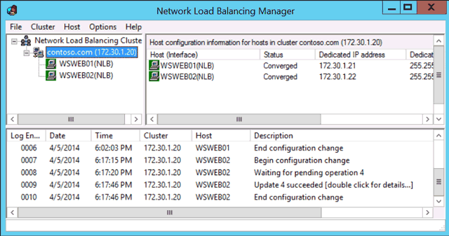
Windows Server 2012 NLB Cluster
Conclusion
In practice, Microsoft’s load balancing feature is handy in development or staging areas, or for those who are just learning about load balancing in general. It can also be used comfortably in production with web application that do not require enterprise features found in other, more expensive balancers.